ArcGIS Utility Network 2026: Telecom & Trace Enhancements

ArcGIS Pro 3.7 | ArcGIS Enterprise 12.1 | Utility Network Version 8

The main telecom-specific addition in the 2026 release is the new Telecom Domain Network, introduced with Utility Network Version 8. It was built specifically for telecommunications infrastructure rather than adapted from other utility models.

1. Telecom Domain Network

Unlike older domain networks that were adapted from electric or gas models, the telecom domain network is designed specifically for telecom workflows. It replaces subnetwork management with circuit management and adds a richer information model for grouping junction objects, edge objects, and associations. 

Classes in a Telecom Domain Network

Feature Classes & Tables

When you add a telecom domain network, four feature classes and five tables are created automatically: 

Class / Table
Description
Device
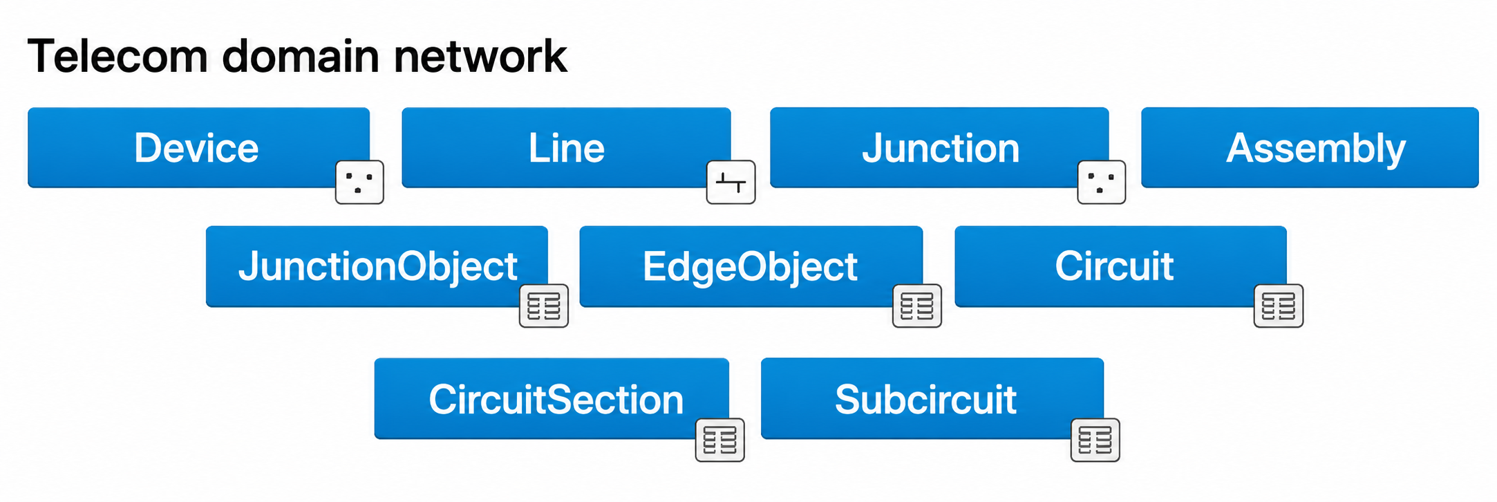
Point features such as switches, optical network terminals, and antennas. These can also act as Junction Unit Containers.
Line
Linear features such as cables and wireless paths. They can serve as Edge Unit Containers with a Max Content Unit ID.
Junction
Connection points such as splice closures, slack loops, and risers that allow mid-span connectivity.
Assembly
Equipment containers such as patch panels and splitters. They can hold devices, junctions, and lines in a spatial context.
JunctionObject
Nonspatial junction objects such as chassis, ports, and splices. These support grouping through First Unit and Last Unit fields.
EdgeObject
Nonspatial edge objects such as fiber strands and copper pairs. These support grouping and foreign-key-based connectivity.
Circuit
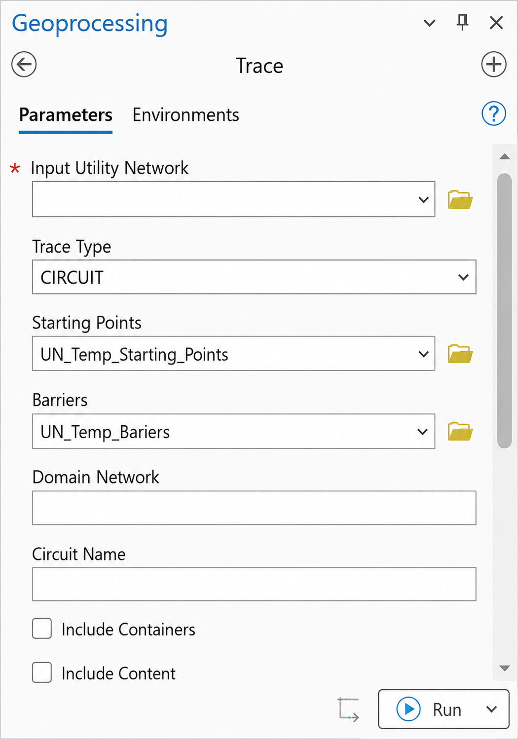
A system-maintained table that stores uniquely named circuits within the domain.
CircuitSection
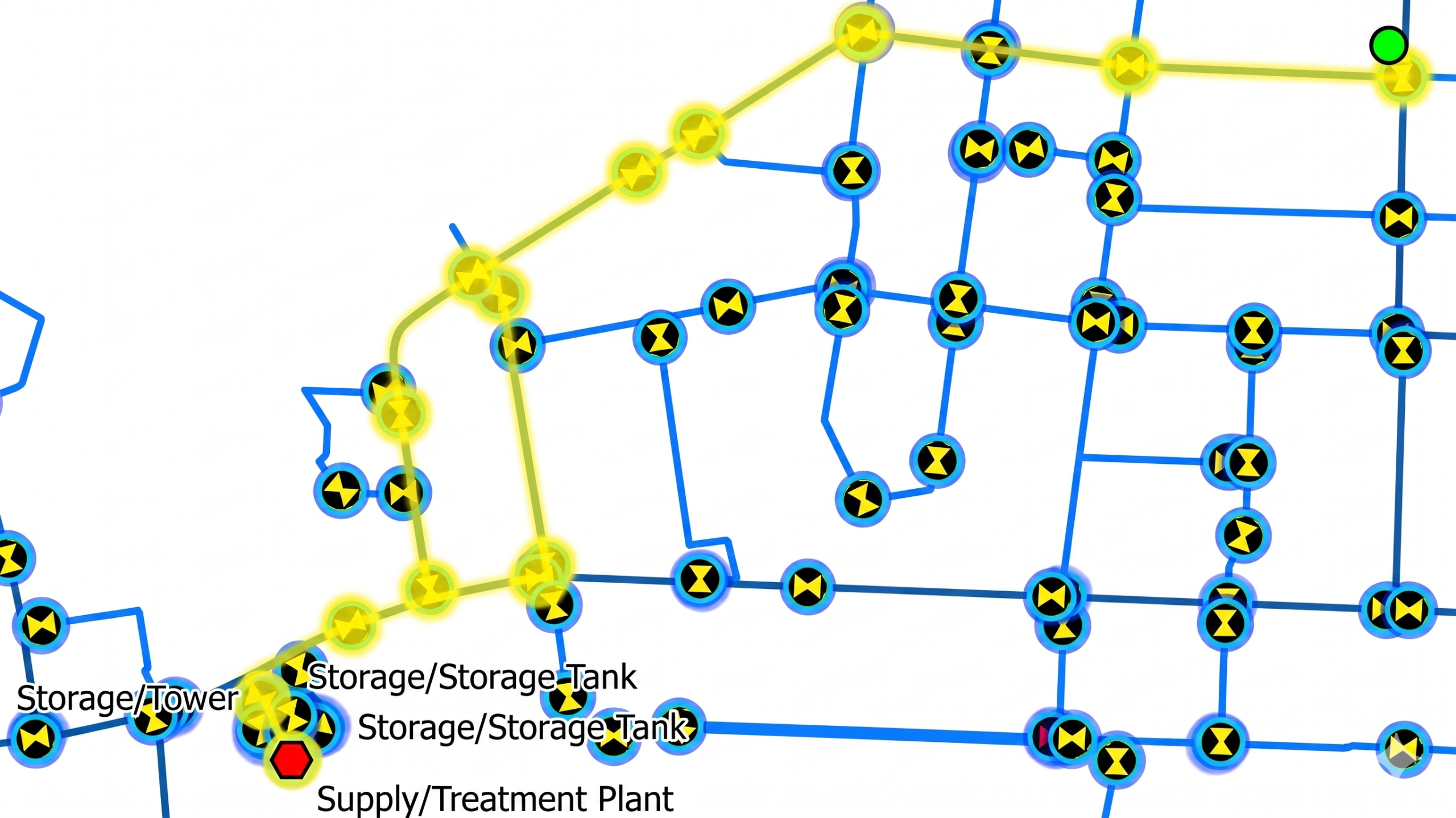
Stores the start and stop locations, along with barriers, that make up each circuit.
Subcircuit
Shows how circuits are divided into child circuits.

Key Capabilities

  • Circuit management replaces subnetwork management, making it easier to track dedicated paths between network elements. 
  • Grouping lets one edge object represent an entire 96-strand fiber cable using First Unit and Last Unit fields, which helps reduce storage and improve performance. 
  • Foreign-key associations store connectivity as field values, which can significantly reduce record counts in large deployments. 
  • Colour schemes support physical cable colour coding on Line and EdgeObject features. 
  • Wavelength schemes support CWDM and DWDM channel plans on JunctionObject and EdgeObject features. 
  • The telecom domain network can also coexist with traditional domain networks, such as electric, within the same utility network. 
Example: Telecom and Electric domain networks in the same utility network

Upgrade Requirement

The Telecom Domain Network requires Utility Network Version 8, which is available with ArcGIS Pro 3.7 and ArcGIS Enterprise 12.1. To use it, you need to run the Upgrade Dataset geoprocessing tool. 

Beyond telecom, the 2026 release also includes three trace improvements that apply across all utility network domain types. 

2. Path Trace (New Trace Type)

This new trace type finds all possible paths between two or more locations in the network. It effectively takes over from the Shortest Path trace, which is now deprecated. 

The new Path trace type in the Utility Network Trace Gallery

The Path trace adds three new parameters: 

Parameter
Description
Stopping Points
Defines the features that act as stopping locations for the path trace.
Num Paths
Sets the maximum number of paths returned between the start and stop locations.
Max Hops
Sets the maximum number of edge-to-edge hops allowed in a returned path.
New parameters added to the Trace geoprocessing tool for the Path trace
Circuit trace tool from the geoprocessing toolbox

 A new Stop tab in the Trace pane lets you define stopping points interactively. If Num Paths is set to 1, the result matches the old Shortest Path trace. If you increase the value, the tool returns multiple distinct paths at the same time.

  • In telecom domain networks specifically, stop locations can also be defined by features with Circuit Location network category assigned — not just explicit stopping points  
  • The Infer Connectivity parameter when used with telecom domain networks to find paths using connectivity inference where explicit physical connectivity isn’t present  
  • Terminal path behaviour (respects valid paths but not terminal directionality) 
Path trace returning 2 paths from a customer meter to a water treatment plant